
Back to: Robotics & Artificial Intelligence (Class X)
Application of Mechanical Block of Robotics.
The Mechanical Block of a robot is the part that gives the robot a body and movement. It includes things like the robot’s frame, wheels, arms, joints, gears, and grippers.
Without the mechanical block, a robot would only be a computer with no ability to move or do work.
Where Do We Use the Mechanical Block?
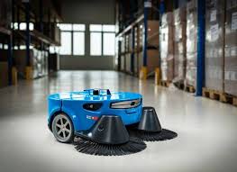
1. To Help the Robot Move
The mechanical parts allow robots to move from one place to another.
Different robots use different movement systems, such as:
- Wheels → used in vacuum cleaner robots, delivery robots
- Legs → used in humanoid robots like ASIMO
- Tracks → used in military rescue robots working on rough surfaces
Example:
A floor-cleaning robot moves around using wheels to clean the entire room.
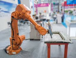
2. To Help the Robot Hold and Use Things
Robots need mechanical parts like arms, joints, and grippers to pick, hold, or carry objects.
Example:
A robotic arm in a factory uses a gripper to pick up parts and place them on a conveyor belt.
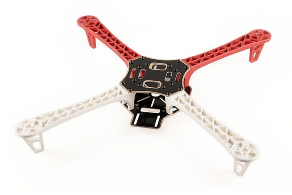
3. To Support the Robot’s Body
The mechanical block provides strength and shape to the robot.
It works like the bones in a human body.
Example:
The metal frame of a drone holds the motors, battery, and propellers in place.
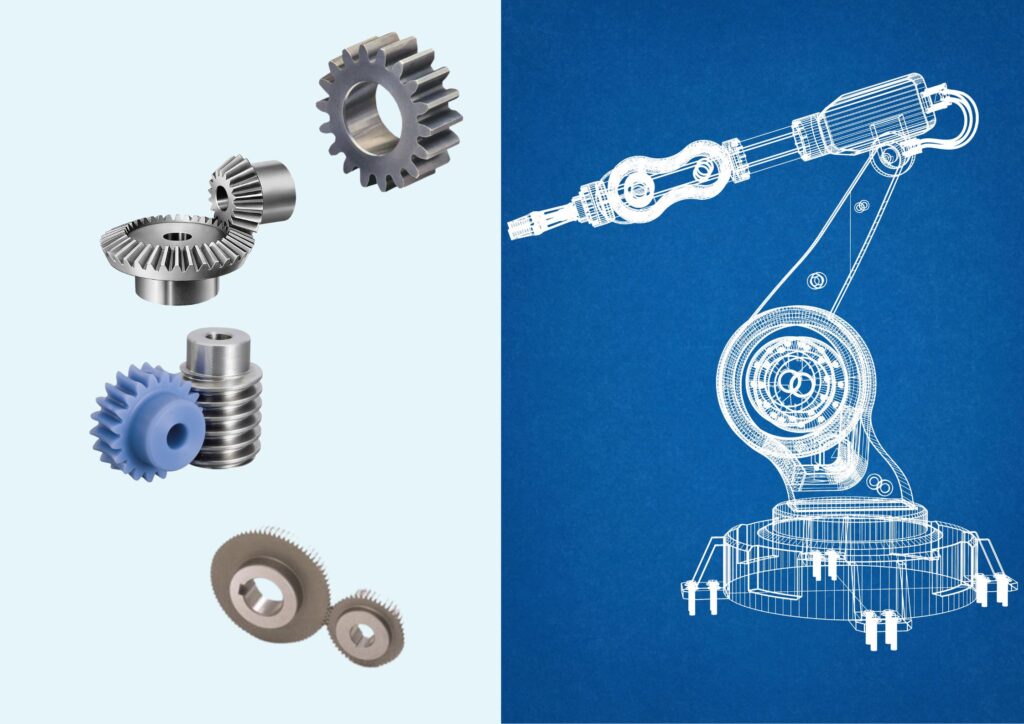
4. To Change and Transfer Motion
Mechanical blocks help change motion from:
- Rotating to sliding
- Fast movement to slow but strong movement
Parts like gears, belts, and chains help with this.
Example:
A gearbox in a robotic arm makes movement slow but powerful so it can lift heavy objects.
5. To Help the Robot Work in the Real World
Robots interact with the environment using tools or end effectors such as:
- Grippers
- Cutting tools
- Welding machines
- Suction cups
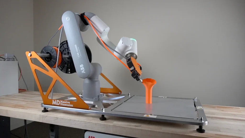
Example:
A 3D printer robot uses a moving mechanical arm to place melted plastic layer by layer to make a model.
Visualize, Design and Create Components of a Robot
Building a robot happens in three simple steps:
1️⃣ Visualize (Imagine the Robot)
Before building a robot, the first step is to visualize or imagine it. You should clearly think about what you want the robot to do and how it will look and work. Ask yourself important questions like: What task will the robot perform? How big should it be? Will it move by walking, rolling on wheels, or flying? For example, if the robot’s purpose is to pick up small objects, you might imagine a small robot with wheels for movement and a robotic arm for lifting items. This visualization helps you plan the design and understand what parts will be needed.
2️⃣ Design (Plan the Robot)
After you have imagined your robot, the next step is to design it. Designing means making a proper plan before starting the actual building. You can begin by drawing a simple sketch of how the robot will look. Then, decide where each part will be placed, such as the motors, battery, sensors, and wheels. It is also important to make a list of all the components you will need. This planning helps you stay organized and makes building the robot easier and faster.
Common parts of a robot:
| Part | Purpose |
|---|---|
| Chassis | Body of the robot |
| Wheels / Legs | Help the robot move |
| Motors | Create movement |
| Battery | Gives power |
| Sensors | Help the robot detect surroundings |
| Controller (Arduino, etc.) | Brain of the robot |
| Gripper / Tools | Helps the robot do work |
Example:
In a line-following robot, the sensors should be placed near the floor and the controller in the center.
3️⃣ Create (Build the Robot)
Once your design is ready, you can start building your robot. Begin by collecting all the required parts and tools. First, make or assemble the body of the robot, also called the chassis. After that, attach the motors and wheels so the robot can move. Next, fix the sensors and the controller board, which will help the robot think and react. Carefully connect all the wires to make sure everything is linked correctly. Finally, test the robot to check if it works as planned and make any adjustments if needed.
If something doesn’t work, make small changes and test again.
Example Project: Line-Following Robot
Goal: Make a robot that follows a black line.
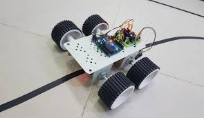
It needs:
- 2 motors + wheels
- IR sensors
- Battery
- Arduino
- Motor driver
Steps:
- Fix motors and wheels to the chassis.
- Place IR sensors in front near the ground.
- Connect motors to the motor driver and Arduino.
- Upload line-following program.
- Test and adjust.
Using Tinkercad to Visualize, Design, and Create Robot Components
Tinkercad is a free, online tool made by Autodesk that helps students and beginners learn 3D design, electronics, and coding in a simple and easy way.
You can access it using just a web browser—no software installation is needed.
1️⃣ 3D Design
In Tinkercad, you can create 3D models by using basic shapes such as cubes, cylinders, and spheres. These simple shapes can be combined and adjusted to form more complex objects. For example, you can design the robot’s body or chassis, create wheels for movement, or even design different parts that can be 3D printed later. Besides robots, you can also build models like houses or any other 3D objects you imagine. This makes Tinkercad a useful tool for learning how to design and visualize real components before building them.
2️⃣ Circuits
In the circuits section of Tinkercad, you can design and test electronic circuits without using real components. This allows you to experiment safely and see how the circuit will work. You can work with devices like Arduino, motors, LEDs, sensors, and buzzers. You can also write and upload code to control the circuit, which lets you test how the robot or electronic system will behave before building it in real life.
3️⃣ Code Blocks
Tinkercad not only allows you to design 3D models and circuits but also lets you control them using block coding. Block coding is a type of programming where you drag and drop colored blocks that represent commands instead of writing text-based code. This makes it very easy for beginners and students to learn programming concepts without worrying about typing errors or complex syntax.
With block coding in Tinkercad, you can:
- Control motors, LEDs, and sensors in circuits
- Program the movement of 3D robot models
- Make simulations run automatically to see how your design behaves
For example, if you have a robot designed in Tinkercad, you can use block coding to make it move forward, turn, stop, or follow a line. You can also program a robot arm to pick and place objects in the 3D simulation.
Using block coding in Tinkercad helps beginners understand programming logic, sequence, loops, and conditions in a fun and visual way. It is a safe and interactive method to learn coding while connecting it to robotics and electronics projects.
Why is Tinkercad Useful in Robotics?
✔ Helps students visualize robot parts before building
✔ Allows testing circuits safely without damage
✔ Helps design 3D printable robot components
✔ Supports programming and simulation
Types of Joints Used in Robots
Robots use joints to move, just like humans use shoulders, elbows, or knees.
Two common types of joints are:
✔ Revolute Joint (Rotary Joint)
- This joint allows rotation (circular movement).
- Similar to a door hinge or robot arm joint.
Example in robots:
A robotic arm rotating to pick and place objects.
✔ Prismatic Joint (Linear Joint)
- This joint allows straight line movement.
- Works like a slider or a drawer opening and closing.
Example in robots:
A robot arm moving up and down in a straight line.
RR Mechanism (Revolute–Revolute Mechanism)
RR Mechanism means the robot arm has two revolute (rotating) joints.
It looks similar to a human arm:
- Shoulder (first rotation)
- Elbow (second rotation)
Why RR Mechanism is useful?
- It can move in many directions.
- It can reach many points in a workspace.
- It is commonly used in industrial robotic arms.
Example in Tinkercad
You can create:
- A base
- First rotating arm (Joint 1)
- Second rotating arm (Joint 2)
- A gripper at the end
You can move and test how the robot reaches different positions.
Visualization of Motion
Visualization of motion means understanding and observing how a mechanical part moves before actually building it in real life.
In robotics, different parts such as wheels, arms, joints, and gears move in different ways. Before making them physically, we visualize (see or imagine) how they will move, so we can check whether:
- The motion is correct
- The movement is smooth
- No parts collide or break
- The movement matches the task of the robot
Why Do We Need to Visualize Motion?
Visualizing motion is important because:
- It helps us predict mistakes before building the robot.
- It saves time, cost, and materials.
- It helps improve the design and working of the robot.
Without visualizing motion, we may build something that cannot move properly.
Examples of Motion in Robots
| Part of Robot | Type of Motion |
|---|---|
| Wheels | Rotational motion |
| Robot arm | Combination of rotation and sliding |
| Gripper | Opening and closing motion |
| Linear slider | Straight-line motion |
Types of Motion to Visualize
Robotic movements are mostly based on two main motions:
1️⃣ Rotational Motion (Revolute Movement)
The part turns around a fixed point or axis.
Examples:
- Wheels of a robot
- Elbow and shoulder of a robotic arm
- Door hinge
2️⃣ Linear Motion (Prismatic Movement)
The part moves in a straight line.
Examples:
- Drawer sliding in and out
- Lift (elevator) going up and down
- Linear robot arm moving forward and backward
Visualizing these motions helps us decide which type of joint or mechanism is suitable.
Using Tinkercad to Visualize Motion
Tinkercad is a helpful tool for visualizing motion because we can:
- Create 3D parts
- Assemble them
- Rotate, move, and test them digitally
This allows us to see how the robot will behave before building it with real parts.
How Tinkercad Helps in Motion Visualization
Tinkercad supports motion visualization in these ways:
✔ 3D Assembly Movement
You can rotate or slide parts to see how they move.
For example, you can rotate a robotic arm joint or slide a linear slider.
✔ Simulation
In the circuits section, you can connect:
- Motors
- Servos
- Sensors
- Arduino programs
Then run the simulation to see how the motor moves the parts.
✔ Collision and Range Testing
You can check whether:
- One part touches or hits another part
- The movement has enough range
- The robot can complete its intended task
Steps:
- Draw the base, first link, and second link in 3D design.
- Add revolute joints where the parts connect.
- Rotate the first joint to see how far it moves.
- Rotate the second joint and observe if the arm reaches the object.
- If using Tinkercad Circuits, attach a servo motor and connect to Arduino code.
- Press Start Simulation to watch real motion.