
Back to: Robotics & Artificial Intelligence (Class X)
Introduction to Gears
Gears are round mechanical parts with teeth that mesh together to transfer movement and force. They are used in machines, vehicles, and robots to control speed, direction, and power.
es and elevators).
Principle of Gears
The principle of gears involves two gears interlocking to transfer motion and force from one to the other. The teeth of the gears fit together, allowing them to rotate together, changing speed and force.
How Do Gears Work?
- Interlocking Teeth: When two gears mesh, the teeth of one gear fit into the gaps of the other, causing them to turn together.
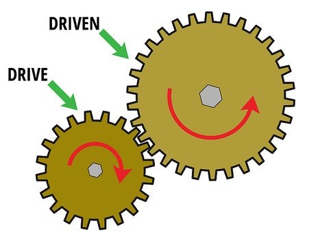
- Rotational Motion: The first gear (called the driver gear) moves and makes the second gear (called the driven gear) turn as well.
- Motion Transfer: This process transfers both motion and force from one gear to the other.
Key Points of the Gear Principle:
- Speed and Force:
- The driver gear rotates faster but has less force.
- The driven gear rotates slower but with more force.
- Gear Size:
- Larger gears move more slowly but give more power.
- Smaller gears rotate faster but with less power.
- Direction of Rotation:
- When two gears mesh, they rotate in opposite directions.
- If the driver gear moves clockwise, the driven gear will turn counterclockwise.
Why is the Principle Important?
- It allows machines to adjust speed and force according to the task.
- By changing gear sizes, we can control the desired speed and power for various tasks.
Example:
In a car, gears control the vehicle’s speed. The engine’s power is transferred through gears, adjusting the speed and force needed for driving.
Types of Gear
1. Spur Gear
- What it is: The most common type of gear, with straight teeth that line up with the gear’s center.
- Where it’s used: In clocks, washing machines, and robots.
- Pros: Simple and easy to make.
- Cons: Can be noisy at high speeds.
2. Helical Gear
- What it is: Gears with angled teeth that allow for smoother and quieter motion.
- Where it’s used: Found in cars, heavy machinery, and industrial machines.
- Pros: Quieter and more efficient than spur gears.
- Cons: Harder to make.
3. Bevel Gear
- What it is: Gears with teeth that are cut at an angle (usually 90°) to change the direction of the movement.
- Where it’s used: In cars, hand drills, and machines that need to change direction.
- Pros: Good for changing direction of motion.
- Cons: Needs precise alignment.
4. Worm Gear
- What it is: A gear with a screw-like thread that meshes with a wheel, reducing speed and increasing power.
- Where it’s used: In lifts, conveyor belts, and tuning guitars.
- Pros: Gives high power and slows down speed.
- Cons: Can wear out and isn’t always efficient.
5. Rack and Pinion Gear
- What it is: A small round gear (pinion) that works with a flat bar (rack) to turn rotary motion into linear motion.
- Where it’s used: In car steering systems and sliding gates.
- Pros: Simple and reliable for straight-line movement.
- Cons: Can wear out with heavy use.
6. Planetary Gear
- What it is: A system with a central sun gear, planet gears around it, and an outer ring gear.
- Where it’s used: In automatic car transmissions and electric drills.
- Pros: Compact and powerful.
- Cons: More complex and expensive.

Gear Ratio
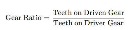
The gear ratio is the comparison between the number of teeth on two connected gears. It helps determine how the speed and power are transferred from one gear to the other. You calculate it by dividing the number of teeth on the driven gear by the number of teeth on the driver gear.
Formula for Gear Ratio:
How Gear Ratio Works:
- Higher Gear Ratio: When the driven gear has more teeth than the driver gear, the driven gear moves slower but produces more power.
- Lower Gear Ratio: When the driven gear has fewer teeth than the driver gear, the driven gear moves faster but produces less power.
Example:
- If the driver gear has 20 teeth and the driven gear has 60 teeth, the gear ratio is:
This means the driven gear will rotate three times slower than the driver gear, but with more strength.
Why Gear Ratio Matters:
- Adjusts Speed and Power: Gear ratios help control the speed and force in machines, cars, and robots.
- High Gear Ratio: Slower speed, but more power (used for lifting heavy loads).
- Low Gear Ratio: Faster speed, but less power (used for quick movement).
Gear Ratio in Real Life:
- On a bicycle, changing gears adjusts the speed and effort based on the terrain.
- In cars, gear ratios help manage speed and power depending on driving conditions.
Sensors in Robotics
A sensor is a device that detects changes in its environment and sends this information to other devices, like computers or controllers. It helps systems understand the world around them by measuring things like temperature, light, motion, or pressure. Sensors are used in many technologies, including robots, smart devices, and vehicles.
How Do Sensors Work?
- Sensors detect specific changes, such as heat, light, or pressure.
- They convert these changes into electrical signals that can be processed by machines or controllers.
Types of Sensors:
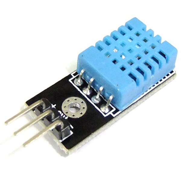
- Temperature Sensor
- Detects changes in temperature.
- Example: Thermometers used in weather stations or air conditioners.
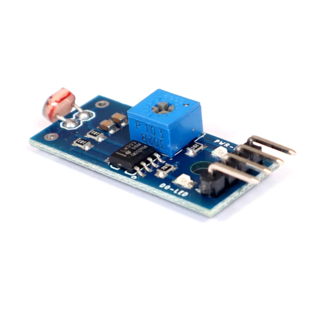
Light Sensor
- Measures the amount of light.
- Example: LDRs (Light Dependent Resistors), used in automatic lights.
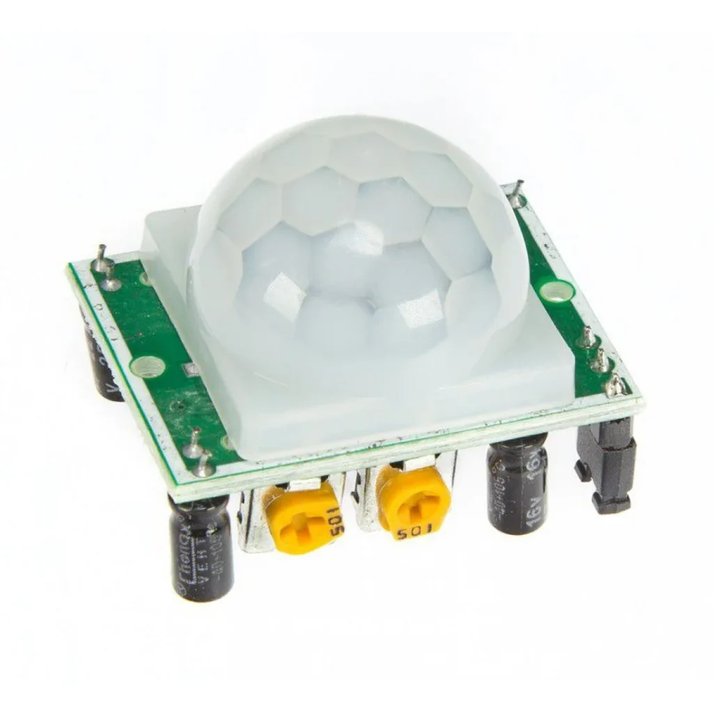
Motion Sensor
- Detects movement.
- Example: PIR (Passive Infrared Sensor), used in security systems.
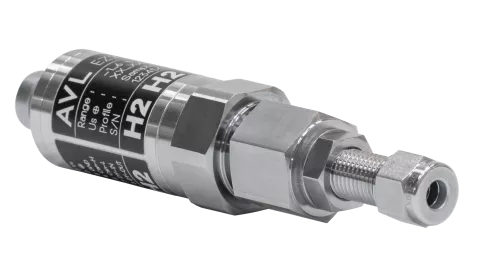
Pressure Sensor
- Measures changes in pressure.
- Example: Barometers, used in weather forecasting.
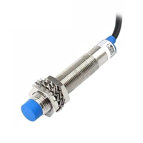
Proximity Sensor
- Detects nearby objects or their absence.
- Example: Ultrasonic sensors, used in robots to avoid obstacles.
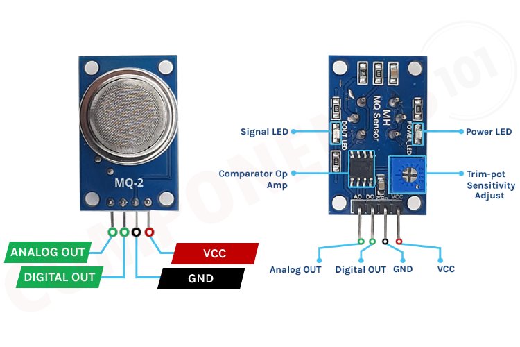
Gas Sensor
- Detects gases like carbon dioxide.
- Example: CO2 sensors, used in air quality monitors.
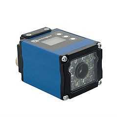
Vision Sensor
A vision sensor is a device that combines a camera with image processing capabilities to capture and analyze visual data. It enables robots and automated systems to interpret images and make informed decisions based on their surroundings.
Example: B50S005
Classification of Sensors
Sensors can be categorized into two main types based on their function and placement within a system:
1. Internal Sensors
Internal sensors monitor the internal state of a system, such as a robot or machine. They help regulate balance, motion, and system performance.
Examples of Internal Sensors:
- Gyroscope – Measures angular velocity to maintain stability.
- Accelerometer – Detects motion, tilt, and acceleration.
- Encoders – Track rotation or linear displacement in motors.
- Current Sensors – Monitor electrical current flow in circuits.
- Temperature Sensors – Measure internal heat levels to prevent overheating.
2. External Sensors
External sensors collect data from the surrounding environment, allowing a system to perceive and interact with external conditions. They are essential for navigation, object detection, and environmental awareness.
Examples of External Sensors:
- Vision Sensors (Cameras) – Capture images for object recognition.
- Proximity Sensors – Detect objects without direct contact.
- Ultrasonic Sensors – Measure distance using sound waves.
- Infrared (IR) Sensors – Identify heat signatures and obstacles.
- Lidar Sensors – Use laser beams to map surroundings in 3D.
- Tactile Sensors – Sense touch, pressure, and force.
Functions of Sensors
Sensors serve a vital role in various systems by detecting, measuring, and responding to physical and environmental changes. Their key functions include:
1. Detection
- Identifies the presence or absence of an object or condition.
- Example: A proximity sensor detects nearby objects without physical contact.
2. Measurement
- Quantifies physical parameters such as temperature, pressure, or speed.
- Example: A temperature sensor measures heat levels in a system.
3. Monitoring
- Continuously observes changes in environmental or system conditions.
- Example: A current sensor tracks electrical flow in circuits.
4. Control and Automation
- Provides feedback to automate operations and optimize system performance.
- Example: An encoder regulates motor speed and position in robotics.
5. Navigation and Positioning
- Assists in determining direction, position, and movement.
- Example: A gyroscope ensures stability in drones and robotic systems.
6. Object Recognition and Identification
- Detects and classifies objects through image or pattern analysis.
- Example: A vision sensor identifies objects in automated inspection systems.
7. Safety and Security
- Enhances protection by detecting hazards or unauthorized access.
- Example: A gas sensor alerts the presence of harmful gases in industrial environments.
8. Communication and Interaction
- Facilitates interaction between humans, machines, and surroundings.
- Example: A touch sensor enables touchscreens to respond to user input.
Actuators
An actuator is a part of a device or machine that helps it to achieve physical movements by converting energy, often electrical, air, or hydraulic, into mechanical force. Simply put, it is the component in any machine that enables movement.
Or
An actuator is a component of a machine that produces force, torque, or displacement, usually in a controlled way, when an electrical, pneumatic or hydraulic input is supplied to it in a system. An actuator converts such an input signal into the required form of mechanical energy. It is a type of transducer (A transducer is a device that converts energy from one form to another).
Types of Actuators:
- Electrical
- Hydraulic
- Pneumatic
Electrical Actuator:
An electric actuator is a device that can create movement of a load, or an action requiring a force such as clamping, using an electric motor to create the necessary force
Hydraulic Actuator:
Hydraulic actuator definition is, a device that is used to change the fluid’s pressure energy into mechanical is known as a hydraulic actuator.
Pneumatic Actuator
Pneumatic actuators are devices that convert the energy of compressed air or gas into a mechanical motion that regulates one or more final control elements.
Applications of Actuators
Actuators are critical components in many systems, converting electrical energy into physical motion or force. They are used in a wide range of applications across different industries. Here are some key applications:
Industrial Automation
- Robotic Arms: Actuators are used to move and control robotic arms in manufacturing and assembly lines, providing precise control for tasks such as welding, painting, and assembly.
- Conveyor Systems: They are used to power conveyor belts and other machinery that moves products through different stages of manufacturing.
2. Automotive Industry
- Power Windows and Seats: Actuators are used in car windows and seats to enable automatic adjustment and positioning.
- Engine Control: They help in managing engine functions, such as controlling throttle, fuel injection, and variable valve timing.
- Active Suspension Systems: Actuators adjust the suspension settings in real-time to improve ride comfort and handling.
3. Aerospace
- Flight Control Systems: Actuators are critical in controlling the flaps, rudders, and other aerodynamic surfaces of aircraft, ensuring stable flight.
- Landing Gear: They are used to deploy and retract landing gear during take-off and landing.
4. Medical Devices
- Prosthetics: Actuators are used in advanced prosthetic limbs to provide movement and functionality, closely mimicking natural limb movements.
- Surgical Robots: They enable precise movements in surgical robots, allowing for minimally invasive procedures.
- Patient Beds: Actuators adjust hospital beds to different positions to enhance patient comfort and care.
5. Consumer Electronics
- Camera Lenses: Actuators adjust the focus and zoom functions in camera lenses.
- Smartphones: They are used in vibration motors to provide haptic feedback.
6. Home Automation
- Smart Locks: Actuators are used in electronic locks to control the locking and unlocking mechanism.
- HVAC Systems: They regulate airflow and temperature by controlling dampers and valves in heating, ventilation, and air conditioning systems.
- Motorized Blinds and Curtains: Actuators automate the opening and closing of blinds and curtains based on user input or environmental conditions.
7. Agriculture
- Automated Irrigation Systems: Actuators control the opening and closing of valves to manage water flow to crops.
- Farm Machinery: They are used in tractors and other machinery to control various functions such as steering and implement positioning.
8. Marine
- Ship Steering Systems: Actuators are used to control the rudder and other steering components.
Actuators are integral to many modern technologies, providing the necessary movement and control in a wide array of applications. Their ability to convert electrical signals into physical action makes them indispensable in industries ranging from manufacturing to healthcare, improving efficiency, precision, and functionality in numerous systems.
A linear actuator is a device that creates motion in a straight line, as opposed to the circular motion of a conventional electric motor. Linear actuators are used in various applications where linear motion is required, such as in machinery, industrial equipment, robotics, and other automated systems. Here are some key points about linear actuators:
Types of Actuator
Linear Actuators
A linear actuator is a device that creates motion in a straight line, as opposed to the circular motion of a typical electric motor. Linear actuators are widely used in applications where precise linear movement is required.
How Linear Actuators Work
Linear actuators typically convert rotational motion into linear motion. The most common type of linear actuator uses a motor (electric, pneumatic, or hydraulic) that drives a screw or lead screw mechanism. When the motor rotates, it turns the screw, which moves a nut along the length of the screw, thereby creating linear motion.
Types of Linear Actuators
1. Electric Linear Actuators: These use an electric motor to drive the linear motion. They are commonly used in applications like adjustable beds, window openers, and robotics. They are known for their precision, ease of control, and ability to hold positions without consuming power.
2. Hydraulic Linear Actuators: These use fluid pressure to create motion. Hydraulic actuators are extremely powerful and are used in heavy-duty applications like construction equipment, aircraft control surfaces, and industrial machinery. They can generate a lot of force but require a complex system of pumps, valves, and hoses.
3. Pneumatic Linear Actuators: These use compressed air to produce motion. Pneumatic actuators are commonly found in automation systems, where quick, repetitive motion is needed. They are simpler and cleaner than hydraulic systems but generate less force.
Applications of Linear Actuators
- Robotics: Linear actuators are used to control the movement of robot arms and grippers, enabling precise manipulation of objects.
- Industrial Automation: They are essential in assembly lines, packaging machines, and other automated systems where precise linear movement is required.
- Medical Devices: Linear actuators are used in devices like hospital beds, patient lifts, and prosthetics to provide smooth and reliable movement.
- Aerospace and Automotive: In these industries, actuators are used for controlling flaps, doors, and other movable parts that require precise linear movement.
Rotary Actuators
A rotary actuator is a device that produces rotational motion. Unlike linear actuators, which move in a straight line, rotary actuators provide angular motion and are essential in applications where rotation is required.
How Rotary Actuators Work
Rotary actuators convert energy, typically from a pneumatic, hydraulic, or electric source, into rotational motion. The actuator’s output shaft rotates, delivering torque to move or control a mechanical system.
Types of Rotary Actuators
1. Electric Rotary Actuators: These use an electric motor to generate rotational movement. They are widely used in robotics, automated systems, and vehicles. Electric rotary actuators are known for their precision, ease of control, and ability to operate in various environments.
2. Hydraulic Rotary Actuators: These actuators use pressurized hydraulic fluid to produce rotation. Hydraulic actuators can generate high torque and are used in heavy machinery, such as excavators, cranes, and industrial presses. They are robust and capable of handling large loads.
3. Pneumatic Rotary Actuators: These use compressed air to create rotational motion. Pneumatic rotary actuators are commonly found in automation systems, where quick and repetitive rotation is needed. They are simple, reliable, and ideal for applications requiring moderate torque.
Applications of Rotary Actuators
- Robotics: Rotary actuators are used to control the joints and end effectors of robots, allowing them to perform tasks that require precise rotation, such as picking and placing objects or welding.
- Industrial Machinery: In manufacturing, rotary actuators are used in assembly lines, conveyor systems, and machinery that require controlled rotational motion for tasks like drilling, cutting, or mixing.
- Aerospace: Rotary actuators are crucial in controlling the movement of aircraft components, such as flaps, rudders, and landing gear.
- Automotive: In vehicles, rotary actuators are used in systems like power steering, throttle control, and valve timing, providing the necessary rotational movement to operate these components.
Controller for a Robotic System
A controller is a crucial part of any robotic system. It acts as the brain of the robot, directing the movements, actions, and responses based on inputs from sensors and pre-programmed instructions. Controllers ensure that all the components of a robot work together seamlessly to perform desired tasks.
Types of Controllers
1. Microcontrollers:
- Microcontrollers are small, integrated circuits designed to perform specific tasks. They include a processor, memory, and input/output peripherals on a single chip.
- Commonly used microcontrollers include the Arduino, Raspberry Pi (though it’s technically a microprocessor), and PIC microcontrollers.
- These are ideal for simple robotic systems, such as line-following robots, where the task is specific and doesn’t require complex processing.
2. Programmable Logic Controllers (PLCs):
- PLCs are industrial-grade controllers used in environments where reliability and durability are crucial.
- They are designed to handle complex tasks in robotics, such as assembly lines, where multiple sensors and actuators need to work together.
- PLCs are programmed using ladder logic, which is easy to visualize and modify for industrial applications.
3. Embedded Controllers:
- These are specialized microcontrollers embedded directly into a robotic system.
- Embedded controllers are designed for specific tasks, such as controlling a robotic arm or managing the motors in an autonomous vehicle.
- They are highly reliable and efficient, optimized for the specific needs of the robot.
4. PC-Based Controllers:
- For more complex robotic systems, especially those involving artificial intelligence or machine learning, PC-based controllers are used.
- These systems use a personal computer to control the robot, providing high processing power and the ability to handle complex algorithms.
- They are often used in research robots or industrial robots requiring real-time processing of large datasets.
Functions of a Controller
1. Processing Inputs:
- Controllers take in data from sensors, such as temperature readings, distance measurements, or visual input.
- This data is processed to determine the necessary action, such as moving a robotic arm or adjusting speed.
2. Executing Commands:
- The controller sends commands to actuators based on the processed data.
- For example, if the sensor detects an obstacle, the controller might instruct the motors to stop or change direction.
3. Communication:
- Controllers often need to communicate with other systems or controllers.
- In complex robots, multiple controllers may be used, each handling a different part of the robot, and they need to coordinate their actions.
4. Feedback Loop:
- Many controllers operate in a closed-loop system, where they continually receive feedback from sensors to adjust their commands.
- This feedback loop ensures that the robot’s actions are accurate and responsive to changes in its environment.
Example Application
Consider a robotic arm used in a manufacturing plant:
- The controller receives input from position sensors that tell it where each joint of the arm is located.
- It processes this information and sends commands to the motors to move the arm to a desired position, such as picking up a part.
- The controller continually monitors the position sensors to ensure the arm moves correctly and adjusts if necessary.
Control Systems in Robotics
A control system is a fundamental component of robotics, responsible for managing and directing the behavior of a robot to achieve a desired outcome. It does so by continuously monitoring the environment, processing the inputs, and adjusting the robot’s actions accordingly.
Types of Control Systems
1. Open-Loop Control System:
- In an open-loop control system, the controller sends a command to the robot without receiving any feedback on the outcome.
- Example: A simple conveyor belt that moves at a constant speed without adjusting for the load on it.
- Pros: Simple and cost-effective.
- Cons: Lacks accuracy since it cannot adjust for changes in the environment or system.
2. Closed-Loop Control System:
- A closed-loop control system, also known as a feedback control system, continuously monitors the output and adjusts the inputs accordingly.
- Example: A thermostat controlling room temperature. It adjusts the heating or cooling based on the current temperature.
- Pros: More accurate and reliable as it adapts to changes.
- Cons: More complex and expensive to implement.
Components of a Control System
1. Sensor: Sensors collect data from the robot’s environment. This data could be anything from temperature, position, speed, to light levels.
Example: A proximity sensor that detects obstacles in front of a robot.
2. Controller: The controller is the brain of the control system. It processes the data received from sensors and makes decisions on what actions the robot should take.
Example: A microcontroller that processes sensor data and adjusts motor speed.
3. Actuator: Actuators carry out the actions decided by the controller. These could include moving parts of the robot, like motors, or activating switches.
Example: A motor that moves a robotic arm.
4. Feedback: In a closed-loop system, feedback is the information sent back to the controller about the current state of the robot or environment.
Example: A speed sensor that tells the controller how fast a motor is spinning.
Examples of Control Systems
1. Temperature Control in an Oven:
Open-Loop: Set the oven to a specific temperature, and it heats up to that temperature without adjusting for external factors like opening the door.
Closed-Loop: The oven continuously monitors the temperature and adjusts the heating element to maintain the desired temperature, even if the door is opened.
2. Robot Navigation:
Open-Loop: A robot follows a pre-set path without adjusting for obstacles.
Closed-Loop: A robot uses sensors to detect obstacles and adjusts its path in real-time.
Importance of Control Systems in Robotics
Accuracy and Precision: Control systems ensure that robots perform tasks accurately and consistently, which is crucial in applications like manufacturing and surgery.
Adaptability: Closed-loop control systems allow robots to adapt to changes in their environment, making them more versatile and capable of handling unexpected situations.
Efficiency: By continuously monitoring and adjusting actions, control systems optimize the performance of robots, saving energy and reducing wear and tear on components.
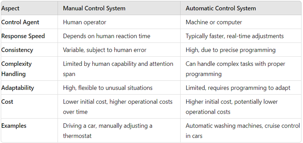
Difference Between Manual and Automatic Control Systems
Control systems can be broadly categorized into manual and automatic systems, depending on how the control actions are performed. Here’s a comparison of the two:
1. Manual Control System
In a manual control system, a human operator directly controls the system, making decisions and adjustments based on observations and experience.
Key Characteristics:
Human Involvement: The operator is responsible for monitoring the system and making control decisions.
Real-Time Decision Making: The operator adjusts the system in real-time based on feedback and current conditions.
Simple Design: Typically requires less complex machinery and components since the human provides the decision-making.
Advantages
Flexibility: The human operator can make decisions based on intuition, experience, and unforeseen circumstances.
Low Initial Cost: Fewer automated components are required, potentially reducing initial setup costs.
Adaptability: Can easily adapt to unusual or unexpected situations that may be difficult for automated systems to handle.
Disadvantages
Inconsistency: Human errors, fatigue, or distractions can lead to inconsistent or incorrect control actions.
Slower Response: The speed of response depends on the human operator, which may not be as fast as an automated system.
Limited Complexity: Managing complex or fast-moving systems manually can be difficult and less efficient.
Example:
Operating a car without cruise control is a manual control system. The driver must constantly monitor speed, traffic, and road conditions, making adjustments to the steering, accelerator, and brakes as needed.
2. Automatic Control System
In an automatic control system, a machine or computer takes over the control functions, performing adjustments based on pre-programmed instructions or real-time feedback from sensors.
Key Characteristics:
Automation: The system operates without the need for continuous human intervention.
Precision: Automatic systems are designed to perform specific tasks with high accuracy and consistency.
Feedback Loop: Often includes sensors and feedback mechanisms to adjust the system’s operations automatically.
Advantages
Consistency: Automatic systems can perform tasks reliably without the variability associated with human operation.
Speed: Automatic systems can respond much faster to changes or disturbances than manual systems.
Efficiency: Automatic systems can optimize processes, leading to better performance and resource utilization.
Disadvantages
Complexity: Design and implementation of automatic systems can be more complex and costly.
Limited Flexibility: Automatic systems may struggle with unexpected situations or require reprogramming to handle new scenarios.
Dependency on Technology: If the automatic system fails, the entire operation may be compromised unless there is a manual override or backup.
Example:
An automatic washing machine is an example of an automatic control system. Once a program is selected, the machine automatically controls the washing cycle, water levels, and spin speed based on pre-set conditions.
Summary of Differences
Understanding the difference between manual and automatic control systems helps in determining which approach is best suited for a particular application, balancing factors like cost, efficiency, flexibility, and the complexity of the task at hand.
Integrating Sensors, Actuators, and Controller in a Robotic System
A robot needs different parts to work properly, just like our body uses muscles, nerves, and the brain to move. In this example, we will see how a robotic arm moves to a specific position using a sensor, a motor, and a controller.
1. The Role of a Sensor
A sensor acts like the eyes of the robot. It checks the position of the robotic arm and tells the controller where the arm is currently located. The sensor used for this is called a position sensor, like a potentiometer or an encoder.
For example, if the arm is straight, the sensor may read 0°. If it moves upward, the angle increases.
2. The Role of a Motor
A motor works like a muscle. It moves the robotic arm when the controller tells it to. The motor can be a DC motor or a stepper motor, which can turn the arm to a specific angle.
3. The Role of a Controller
A controller is like the brain of the robot. It decides how much the motor should move based on the sensor’s readings.
How It All Works Together
Let’s say we want the robotic arm to move to 90°:
- The sensor checks the arm’s current position (e.g., 0°).
- The controller compares it with the target position (90°).
- If the position is incorrect, the controller tells the motor to move.
- The motor rotates the arm.
- The sensor continuously updates the controller on the arm’s position.
- When the arm reaches 90°, the controller stops the motor.
Example: Robotic Arm
Let’s walk through a simple example to understand the integration of these components:
- Step 1: The position sensor continuously monitors the angle of the robotic arm’s revolute joint.
- Step 2: The controller checks the sensor data to determine if the current position matches the desired position.
- Step 3: If there is a discrepancy between the current and desired position, the controller sends a signal to the motor to adjust the arm’s position.
- Step 4: The motor drives the revolute joint to the desired angle.
- Step 5: The position sensor updates the controller with the new angle, and the process continues as long as adjustments are needed.