
Back to: Robotics & Artificial Intelligence (Class IX)
Component Required:
- LED
- Resistor 220 ohm
- Jumper Wire (Male to Male/Male to Female)
- Bread Board (Optional)
- Arduino
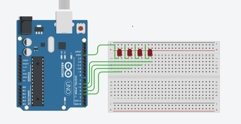
The objective of this project is to program an Arduino microcontroller to control multiple LEDs in a specific pattern sequence. This project aims to teach students how to:
- Understand how to connect multiple LEDs to an Arduino and control them via digital output pins.
- Write a program to create different LED patterns using Arduino, such as blinking sequences, running lights, or alternating flashes.
- Utilize loops (
for,while) and conditional statements (if-else) to manage complex LED patterns. - Develop programming skills for controlling multiple outputs simultaneously.
- Understand timing and synchronization using the
delay()function and explore how to manage multiple delays.
Programming Step:
Initialization of pin;
- int L1=3;
- int L2=4;
- int L3=5;
- int L4=6;
pinMode();
- pinMode(L1,OUTPUT);
- pinMode(L2,OUTPUT);
- pinMode(L3,OUTPUT);
- pinMode(L4,OUTPUT);
Logic
- digitalWrite(L1,HIGH);
- digitalWrite(L2,LOW);
- digitalWrite(L3,HIGH);
- digitalWrite(L4,LOW);
- delay(1000);
- digitalWrite(L1,LOW);
- digitalWrite(L2,HIGH);
- digitalWrite(L3,LOW);
- digitalWrite(L4,HIGH);
- delay(1000);
Programming
int L1 = 3;
int L2 = 4;
int L3 = 5;
int L4 = 6;
void setup()
{
pinMode(L1, OUTPUT);
pinMode(L2, OUTPUT);
pinMode(L3, OUTPUT);
pinMode(L4, OUTPUT);
}
void loop()
{
digitalWrite(L1, HIGH);
digitalWrite(L2, LOW);
digitalWrite(L3, HIGH);
digitalWrite(L4, LOW);
delay(1000);
digitalWrite(L1, LOW);
digitalWrite(L2, HIGH);
digitalWrite(L3, LOW);
digitalWrite(L4, HIGH);
delay(1000);
}